Thursday, 3 June 2021

External renovation of the North Signal box at Boat over 31May and 1June

External renovation of the North Signal box at Boat over 31May and 1June


By Colin Frost 


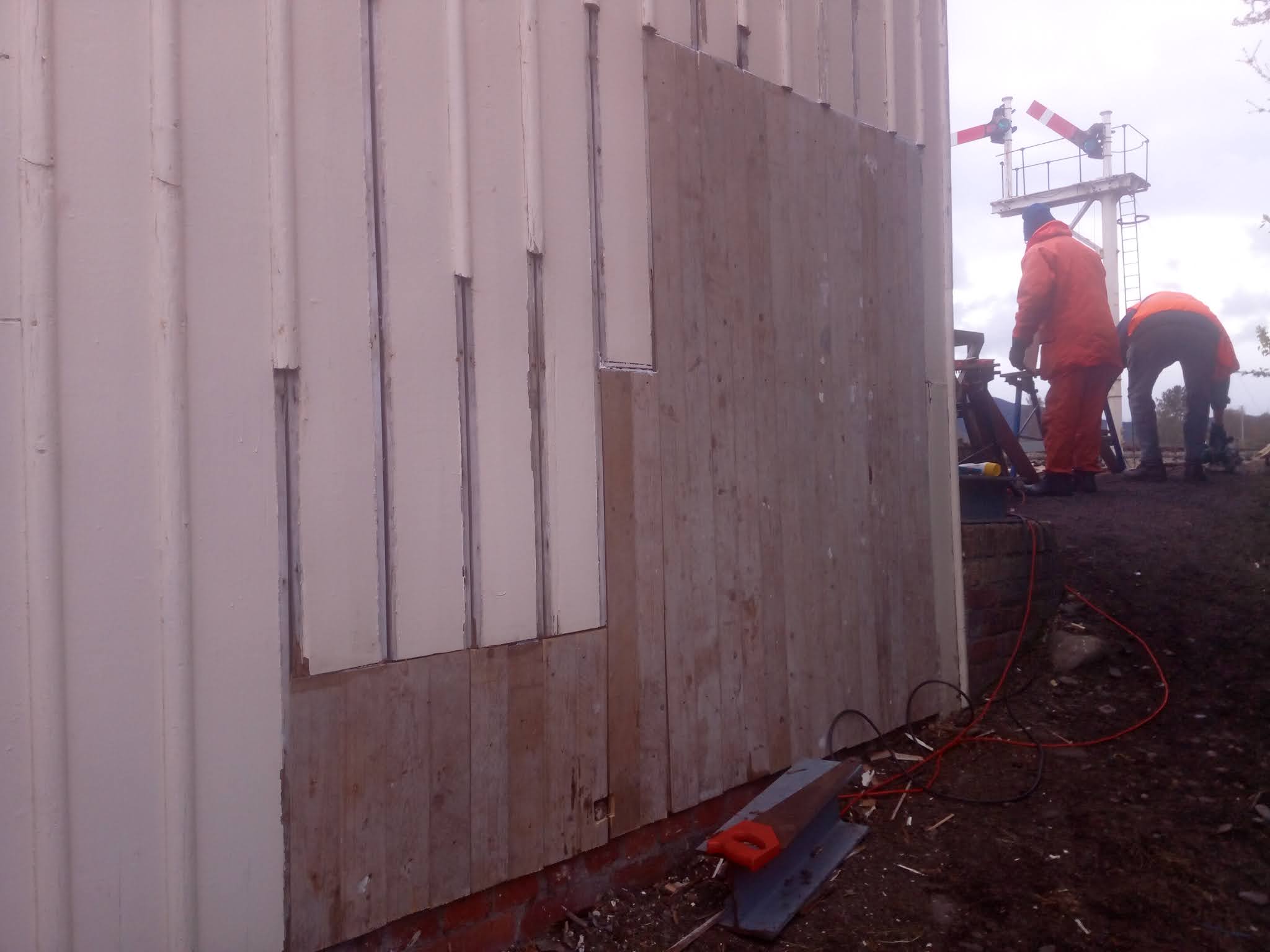
Taking advantage of the sunny weather, Ray and Colin spent a further two days catching up on work that that had been postponed due to the previously inclement weather of a last couple of weeks ago.          


The final colours have been applied to staircase and work has progressed painting the token stand, which has been in bare wood since its construction probably over 5 years ago.


Further sections of the rotten moulding have also been cut out and replaced, but for the time being this is about all that can be done, until the scaffold has been erect, which is scheduled to be in place from 17June.


More next time..........

Progress! Progress! And a spanner in the works...

Progress! Progress! And a spanner in the works...

By Robert Law

2 June 2021


It has been a while since my last update but lots have been achieved. Lot of pictures for you to see! To start with credit needs to be given to the other departments that have been getting involved with what has tuned into a big project. Colin Frost and Co have been getting stuck into the much needed building maintenance and timber renewal of the North Signal cabin structure. Please have a read of the dedicated posts on this work. Then there is our E&P team lead by Nick Winter. Who I have to say, has done a brilliant job of bringing the power and distribution of the signal box right up to current standard. Unfortunately there has been a operations mishap by our locomotive department but this have been dealt with very quickly and efficiently by both P-way and S&T teams with normal working resumed by the next day.


The picture dose have a signal in it! Number 19B of Speyside cabin, with our black 5, 5025 shown here doing test runs within the station area of Aviemore. The annual Maintenance and FPL testing has been completed at Aviemore Speyside and both Station ground frames, with the shed staff “playing trains” around us. 


Back to Boat of Garten North Cabin. Work has progressed on connecting up the points indication circuit. Which has now been connected up, with the addition of electrical locks now working on 4, 7 and 16 signals. This is the three signals that protect the points. Now the mechanical interlocking checks that all the levers in the lever frame are in the correct position. With the electrical detection at the points proving that the points lever has put the points over and that the points lock lever has in-gauged the lock. Thus making sure that it is safe for trains to travel and stops signaller’s from doing anything that they should not.

The track circuits that are required to prove that no train is present over the points, will be installed in the near future. This has been delayed by the weather and S&T HQ not been able to work outside in the rain. But now that the points detection is installed there is no need for the use of the clamp and scotch making our P-way department much happier when taking their trains in and out of their site.


Underneath the cabin, lot’s has been going on Nick Winter’s new power distribution clear to see by the front door, new LED strip light meaning that we can now see! What a difference in light output compared to the old lights! The New S&T power distribution board is now live and work can now commence on moving the current signal lighting circuits over to the new board. Plus the B12 supply for the electrical locks and relays is now feed from the new supply.


S&T power distribution board. 110v external, supply to the signal location cases when they arrive, to the left. 24v signal lighting in the middle still to be completed. On the right B12 supply for the internal lever locks and relays.


A look upstairs showing the new 1950’s style signal cabin lighting. This is a vast improvement compared to the original strip lights that was in the cabin. There are still period type lamp shades to go on and the  “old” current signal lighting switch still in place which will be removed once the control circuits have been moved onto the new power distribution board.


Looking to the north of the box you can see the signaller do get a light for the writing desk, for filling in there paperwork. The old Tilley lamp is still sitting on the original hook just to remind people of what the cabin originally had for lighting before the Strathspey Railway put electricity into the box. That’s right under BR this signal cabin never had a 240v mains supply. The other question some of you may ask, “why only two small lamps”. Simple, to reduce the light pollution. So the signaller can see out his windows at night. To see what train is there if it is clear of the signal and if it’s train is complete, and the tail light is showing. Note to signaller’s you now have a plug, table and seat to sit in for your cup of tea! No need to deserted your post now!


Unfortunately, in the first week of service there was a operational mishap. Probably not the best thing to be showing! But it shows how the railway pulls together to get things fixed and safe for the public in the most efficient way. When the train was making it’s run round movement at Aviemore. A bit of memory fog came over a member of staff which lead to the damage of the points at the North end of Aviemore station. Unfortunately damaging the stretcher bars, lock bar and right hand switch blade. In this picture the p-way have already removed some of the S&T equipment. Clamping the points making it safe for the train to depart in a trailing movement. (From the back of the picture, to the front). Once the train was out the way both S&T and p-way got to work to get things fixed before the train was to return.


By the time the train was to return, replacement stretcher bars were on. Heat treatment had been applied to the bent switch with the correct pressure applied to bring it back to its correct shape. With this been achieved a clamp and scotch was fitted making it safe for the service train to pass over in a facing movement. With the happy passengers now back in Aviemore, the train that had now finished for the day was shunted away for the day allowing us to continue with the repairs. By 19.30 the points were back into original condition apart from a bit of welding that was required to build up the damaged right hand switch blade. The local blacksmith came out at 08.00 the next morning to successfully make this repair. The FPL was setup and tested. Once this work was completed and trains were running the next day from 10.00 with no one knowing any different. This was a bad situation, but it is a good example of how team Strathspey can come together to keep trains running.


CR828 passing over the repaired points after a 7 day exam had been made on the North Station GF after the event. All nuts checked for tightness and a second FPL test carried out, to insure everything was ok. Which it was!


Monday, 31 May 2021

External renovation of the North Signal box at Boat between 10 and 20May


 External renovation of the North Signal box at Boat between 10 and 20May


By Colin Frost 


With the majority of the defective timberwork replaced, it was time to commence painting the newly repaired sections.  So Ray Kenyon and Colin Frost spent four days each week working on this between very frequent periods of rain, not conducive to paining!


Having removed a metal workbench from against the wall we found another small area in need of replacement and also a step in the staircase needed to be cut out and replaced.  At least these jobs could be completed when it was too wet to paint.  The timber for the step was neatly cut by Willie Dodds in the carriage shed on the big saw and a spare step is now stored in the under croft for when it might be needed. 


Dave Childs also brought along a quantity of new half-round mouldings, and some of these were fitted, but there will be many more to do later, when the scaffold is up.  


By the tenth day primer and two coats of undercoat had been applied to all the new timber and also to the staircase which is now awaiting the top coat of brown.


The store shed on the north end of the building was also painted with the final top coats applied. 


More next time..........


Tuesday, 25 May 2021

External renovation of the North Signal box at Boat between 02 to 06 May

External renovation of the North Signal box at Boat between 02 to 06 May


By Colin Frost 


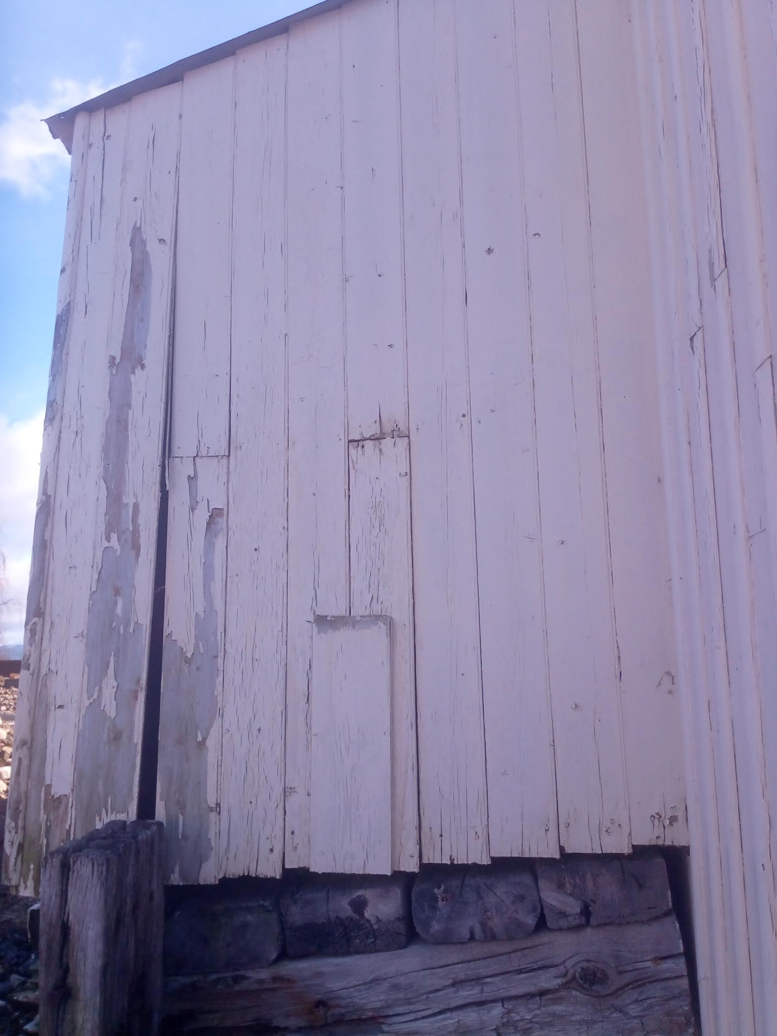
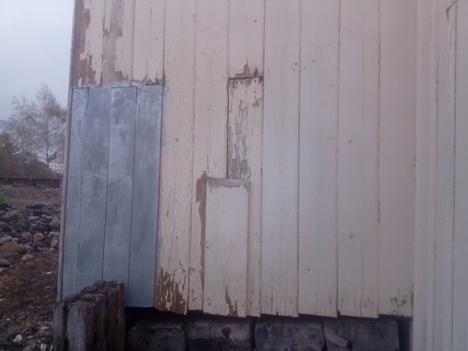
The exterior of the box is generally in a poor state of repair, with a good proportion of the lower half of the external cladding of the building (which consists of tong and groove boards) beyond saving, and with many of the vertical cladding strips also in need of replacement, and all needed to be replaced before any painting is attempted.


So three of us Jim Hardy, Ray Kenyon and Colin Frost of the Ellon Team commenced cutting out the rotten timber sections, which were mainly on the back wall of the building and with great assistance from Dave Childs, who provided his nail gun and also placed the order for new the half-round mouldings, we fixed replacement timber to these sections.


The timbers at the bottom of the stair case were also rotten, to an extent that the left-hand support post at the base of the stairs was in danger of collapsing entirely.  A new post was fitted and further vertical strengthening added.


The store shed on the north end of the building was also in need of the same attention with the floor also beginning to collapse.


More to follow next time :-

Tuesday, 27 April 2021

Preparing for the electrical interlocking.

 Preparing for the installation of the electrical interlocking.


27th April 2021.

The project is progressing in several areas at the moment. The two location cases that are to be installed are currently off site at Strathspey S&T’s HQ. Unfortunately I don’t have any pictures for you but I can inform you that the locs have been cleaned down and repainted. The equipment that was in them has been removed. Installation of the track circuit and points detection equipment that is required is currently been installed and the location cases will arrive in a plug and play form. Only the external wiring will need to be connected up once on site. On-site various parts are still being removed, replaced and installed. See the pictures below.


The relay cabinet has seen some attention with it being cleaned down to start with. Some parts that are not required have been removed. The cabinet has had a good clean out, wash and polish. As you can see in this picture, the before and after is quite a improvement. The doors for the cabinet are also down south at S&T HQ. They will be coming north with the location cases. The relays that are required have been looked out of our store and placed in the cabinet. Two polarised relays for the points detection and three others for the track repeat relays and the route release from Boat Of Garten South signal box.


The cable termination board that was in the relay cabinet was life expired so a new one needed to be made up. Again this was done as a homework project off site, thankfully got the measurements correct. On this board there will be the B12 and N12 for the relay control circuits and lever locks. Below that will be the two 19 core cables going to the location cases and 4 wires to the South signal box. This runs to the south box over our telegraph pole route between the two signal boxes, which extends as far as Aviemore.


Once the board was installed into the relay cabinet the two 19 cores cables were terminated this is how it was looking. Still lots to do with the internal wiring yet.


The catch handle has been fitted onto number 3 lever, the yard points FPL. This acts as a switch to energise the release circuit of its own lever lock. If the track circuit is not clear then the points can not be moved.


The catch handles for the signals over the points has been installed too. These ones are behind the frame as a electrical release is only required to pull the levers, not to return them to danger. 


Down stairs. The two transformers for the 110v external and the 24v signal lighting circuit have been boxed, fitted and are ready for use. The current B12 supply has been moved from it’s original position and is now on the new S&T power distribution board. Just require the E&P department to supply us with 3 spurs form the 240v consumer unit to power up.


The p-way has received the step plate IRJ’s that were required to complete the track work for the track circuits. All have now been fitted and are ready for the track circuits to be energised. Once we have received the location cases from S&T HQ!


With us having some much needed better weather, the black paint at the bottom of the signal posts has been applied. Visually, definitely an improvement.


Thursday, 1 April 2021

Mechanical Interlocking Completed!


Mechanical interlocking completed 

1st April 2021


It has been a very interesting part of the overall project this one. I now have a big appreciation for what the locking fitters of old and current do. First of all the planning of the work, then doing the work. There is very little room for error when creating the locking bars as well as the cutting of the notches in the tappets. Then trying to fit the locking bars in the channels, some of the locking bars designed to fit under the tappets and the others on top of the tappets. It has been a very challenging job indeed.


This is how we were looking at the end of the weeks work, the stop board removed from the end of the up platform and the new DN starter on the up platform brought into use as it is solely controlled by the mechanical interlocking. 4 7 16 still require the electrical interlocking to be completed before being brought in to full use.


This is a look at one of the newly made locking bars. This one is for insuring that 2 points are set for the main line and that 3 FPL is reverse. Only then can 16 signal be pulled or 12 the King lever for locking out the signal box. This is for single line working from Aviemore to Broomhill.


This is one of the existing locking bars that had to be modified. Before it was 8 signal locked 19 points. Now that it has been changed it is 8 signal locks 17 signal and 19 points. There is a second bar that locks 8 signal to 18 FPL.


This is the before and after of cutting the notch on 2’s tappet. The lock piece is used to give the size of the notch that needs to be cut. This notch is for the locking bar between 2 and 7 signal insuring that 2 points are normal before 7 signal can be pulled. 


Once all the new and modified locking bars and the tappets with there notches cut in the correct positions. This is how both the top and bottom locking boxes were looking. In my opinion it is one of the most important parts when it comes to signalling. With out it, it would be almost impossible to run the trains safely.


This next little video is NOT the full locking test but it gives you a feel to how much goes into this. A full independent interlocking test was done after this video was shot, by a college who was not involved in the work. The mechanical interlocking was found to be working correctly and fit for purpose.


This is a very big step forwards. Next we will be moving onto the electrical interlocking. This is required to supplement the mechanical interlocking to insure that safety is maintained.


Tuesday, 23 March 2021

Boat of Garten North Interlocking

 Boat of Garten North Interlocking 

21 March 2021


It has been a while since the last update, progress has been slow with the forever changing situations. Anyway progress has been made! A lot of time has been spent making up drawings to work from, in regards to the interlocking. It has taken a lot of drafts, emails and discussions with colleagues but in the end I believe we have a working plan for the interlocking for the north signal box. 

For those who do not know or understand what “interlocking” is. Basically it is what determines if the train can be signalled from signal A to signal B. I suppose you can call it a mechanical computer, only if the levers are in the correct position and have been pulled in the correct order will you be able to pull off the signal allowing the train to move.


Just a reminder for us all this is what we are working towards. Still lot’s to do but it will be good when it is all finished. 


This may not look like much but a lot of time and effort has gone into this, by several people! Each picture is one locking box. This is the diagram of what needs to be done to allow train’s to run safely preventing any conflicting movements and ensuring that the signaller can only do his job correctly.

We have been lucky to find some locking tappets in one of our store vans. Which have had the old notches cut off and new metal bar added, so they are as good as new! Other than needing cleaned and polished up they are ready for use. Thank you who ever took the time to do all this work in the past, it is much appreciated.


This is how we were looking after a day had been spent cleaning up the tappets. At this point the pins still needed cleaned up and pin holes skimmed out. This was all completed and they were taken back to the signal box at Boat Of Garten to be trial fitted.


With out the new tappets in, this is how the locking looks in the locking boxes. So what you can see in the top locking box is two channels for the locks to sit in. Thus allowing you to have up to four locks on one tappet if required. You can just make out the “locks” the “tappets” and the bars that hold it all together. It’s not the easiest to get a picture of because of its location and certainly not the easiest to work on.


Not the easiest thing to show in a picture but this is all the tappets that we require in the locking boxes. The locking boxes are of a Eastern Region design, on our Mackenzie and Holland frame. This was quite a common thing with the frames that had been sent to Crew to be serviced and prepared for the next signal box that it would be installed in.  The tappets are not straight, there is a curve half way along them because of the way the lever moves in the frame. Each tappet in turn needed to be shaped as required for a smooth movement from the normal to reverse position. After a lot of removing, shaping and replacing this was finally achieved.


With the tappets all in the locking boxes sitting ready for the notches to be cut to take the locks. It was time to start looking at making up the locking bars. Hear you can see a selection of the different shape locks and the bars that hold them all together. This is what prevents or allows the levers to be moved.


This is the first attempt of riveting the dies to the bars, not a bad attempt a lot has been learned and will see about doing it for real next time.