Saturday 25 July 2020

Boat of Garten, North Box, Signal Work

Signal works for Morley’s!

The work done at present is a bit like a wind up clock , each part needs to be working in unison to create functionality and so little tedious jobs that are time consuming have as much benefit to the project albeit unseen.


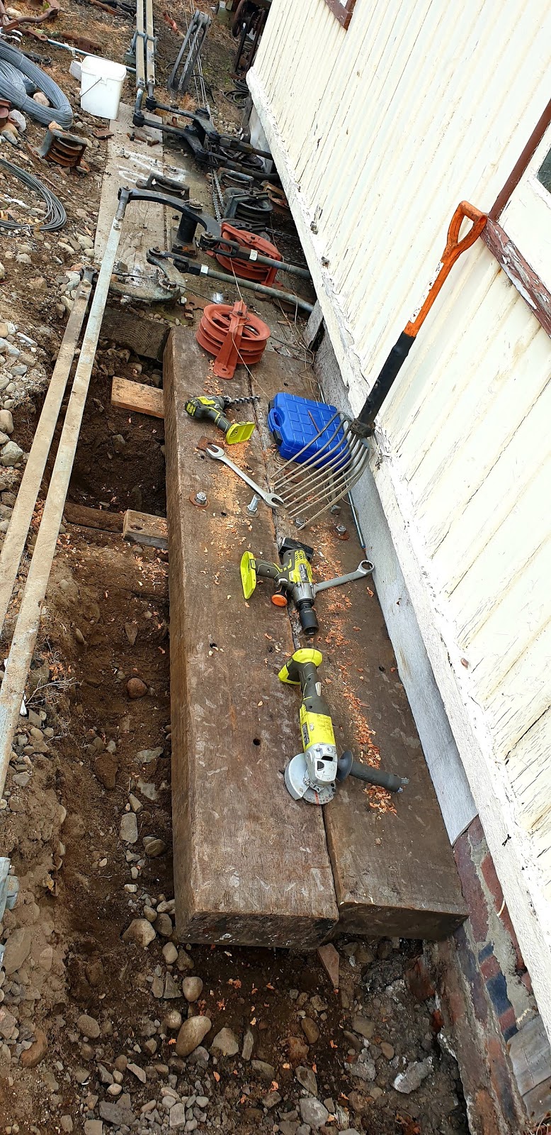
The first of the unseen Jobs was to get the pedestal wheels in under the box. Not the simplest of jobs to do! With the aid of string lines, rulers and power tools. Each wheel has been placed into it’s correct position, for receiving the wire from the lever tail and passing it out to the flat wheel outside. Which then sends the wire on it’s way to the signal. If anyone of these parts is out of alinement, then the harder the pull on the lever will be. As well as more likely to have faults in the future. Within this picture you can see that all the pedestal wheels have been placed and screwed down.

The way that the existing signals have been attached to the lever tail is with chain and S clips. To maintain the look and to keep everything uniformed. The same Practice has been applied with the new signals that we are putting in. This is a picture of the first trial fitting. It took lots of attempts to get the correct length of chain for each lever but with a bit of perseverance it all came right.


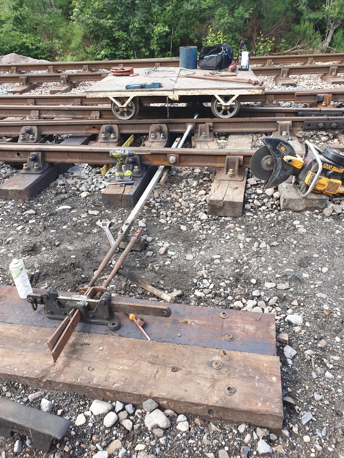
On the outside of the box it was found that the front table needed to be extended to get the flat wheel on for number one signal. So more digging, drilling and power tools. Two new timbers Where added, all just for one wheel. Although now looking at it. It dose tidy up the front of the box and makes it look like it has a much bigger frame within the signal box. As it did back in the day. Also in this picture you can see how the flat wheels have all been placed out first, with the aid of string lines to get the correct position. The other problem that complicates things is the need to get the wires in the correct order. Signal number 16 needs to be the wire nearest the signal box as it is the signal closest. As well as the signal being on the left hand side of the wire run. Then signal number 4’s wire needs to be the second wire from the signal box side. It is the second closest signal and is on the left hand side of the wire run. Both signal wires for 1 and 7 signals both go over the bridge. 1 drops away with a flatwheel on its left to go under the track to the signal. This is the third wire from the signal box side. While 7, the closest to the track, runs on it’s own all the way to the outer home. It’s been a lot of tea drinking and drawing sketches on the back of envelopes but I hope it all works out well.


Hear you can see the completed job from the outside. All the flat wheels are screwed down, chains or wire ropes coming out from the lever tails. For 17 all that is needing to be done is to run the wire run. Everything is now in place. All other pedestal wheels, flat wheels and wire pulleys are all in place. 16,7,4 and 1, there is still some work to do. The stakes need to be put in the ground every 9yrd to hold the wires( about 50 to put in). The wire pulleys to be fitted to the stakes, Two flat wheels to be positioned And screwed down, for number one signal. Plus a some other jobs! The list is getting smaller!

Davie Dow has helped out with creating and mounting of the pulley in the middle of the bridge to take the signal wires. For this I am most grateful.


 A little bit more work has been done on the outer home. With the ladder now up, and signal arm put on. This in it’s self was no easy task as the signal is 28ft tall with a ladder of 29ft ish, at an incline of  1 in 12. This is the standard for this type of LMS post. The arm will be bagged up before any trains are running and will only be de-baged when coming into use. Once the project is completed. This is  hopefully at the start of next season.

Sunday 12 July 2020

Morley’s sidings

Morley’s sidings. 12/07/2020

Time for another update on how work is progressing on the Morley’s sidings project. As you will see in the pictures below things have been progressing well. It’s like a mercano set! Everything fits together but you just need to find the correct parts. There has been a lot of time spent going around the railway looking for the correct parts but the end result for this has been Very good.

So the first of the jobs was to get the drop lugs on the points ends facing the correct way and to get the alinements correct between the points to the detector. As well as the alinement of the wire run from the detector to the base of the signal.


 This is the first attempt at getting the alinements correct, unfortunately this did not work out. The connection rods and swords just did not fit well for the job. So it was time to look for better parts on the railway.


This is the finished job! Detector is fitted, better swords and connectors Rods was found and replaced. Points were tested and correct. Very happy with the outcome. Just to remind you all. The threaded bar at the front of the points is acting as the sole plate to ensure that nothing can move.


 Now this is a hard one to explain, at this point some time was been spent sorting out cables for between the signal box and the two location cases that have been installed at the new outer home. 400 yards of 19core and 400yards of 2 core cable have been prepared which the P-way were ask to  help pull out.
 The hope was to get a bit more done on the outer home but unfortunately it was not to be. The ladder that had been selected for it turned out to be to badly damaged. Another needs to be found. With it been on the roadside for all to see, would prefer it to be as perfect as possible.
Still managed to get the balance weight up and mounted. It’s not much but it’s a step in the right direction.


 This is the new section starter now with it’s ladder fitted. The hoop at the top is damaged and needs replaced, which I anticipate to have done on my next visit and weather permitting a coat of paint.
This signal I am really getting quite fond of. Now fitted with it’s ladder, balance weight leaver and crank fitted at the bottom. All that it left to do with this signal is the wire run and the signal lightning circuit.


A little bit more  has been done on the “A” end of the points , I’m really pleased to how this has turned out. On the left hand side of the picture you can see the newly pulled out cables running from the signal box to the outer home. The cables still require to be jointed.

 This photo was supplied curtesy of Graham Maxton . He has challenged us to recreate this picture. Would it be easier to create  it from the signal box or from up one of the signals?
 This picture is from the new section starter, I believe that the  previous or original Starter signal was on the north of the old bridge. The new shed sits on top on the old sheds foundations.
 This is the view from the North signal box so I don’t think the original picture could have been taken from hear.
 Again this is taken from up the top of the new section starter but this time looking south towards the station. Been qualified and permitted to build and climb these structures is definitely a perk of the job. You can appreciate what the railway has and what “Team Strathspey” has created.
 A bit of time has been spent cleaning out the North signal box. Getting all the equipment that should not be on the operating floor out. If anyone is willing to help and enjoys painting then hear is a nice little job for you. Please let me know if willing to help.
 Looking from the opposite end much better but still some work to be done.
The S&T vans on the way back to the sidings at the south end of the station after collecting all the materials out of the North signal box.

Thursday 2 July 2020

Detection of points


Morley project.

Detection of A end of points.

To say this has been simple. Straight forwards! Was not a problem at all! Well not quite. This has been challenging to the last nut and bolt. With several rethinks and a lot of tea drinking. Still it’s in and meets with the specifications that must be achieved. It requires to be Electrically wired up yet, as well as the electrical interlocking within the signal box still to do.

This is the HJ Detector, I would have liked to have installed. It came over the fence from the Networkrail Aviemore project. It was part of the redundant materials that the Strathspey was given. Unfortunately it is set up to be on the left hand side of the points as you look at them. It can not be changed to a right hand mount without the locking bars been swapped out. The reason it can not be fitted on the lefthand side is simply, the points rodding is in the way.


This HJ detector was looked out from our store, was not in the best of condition. Although it is set up correctly to be on the right hand side of the points and contains the correct locking bars that can be swap out. But first will clean it up and see if this on can be fitted.


Before having a good looking at the insides of the HJ detector. The mounting brackets of this detector required to be removed. Unfortunately the mounting brackets are of the wrong type for the type of rail and buckled beyond repair. Managed to get three of the nuts off, there are four in total. One in each corner. The bolts, where stuck fast and an angle grinder needed to be applied to cut them all off. Unfortunately they would not knock out with out a lot of pressure being applied. The problem being that the body of the detector is cast and is likely to fracture if to much force is applied. A much kinder approach was required. Drilling a hole through the old bolt to weaken it, allowing it to collapse in on it self. Reducing its hold and allowing it to be knocked out with out damaging the casting.


Making progress! All four bolts out, now to have a good look at the insides.


Stripping it down reviled a few problems with corrosion on key parts.  ThIs is the unfortunate part of it being in storage for a long time out in the open. Some parts Where heavily pitted and some of the “fingers” the electrical contacts broken.


Corroded parts that needed to be swapped were swapped. The fingers changed over to the other body and a good clean. This is how it was looking before putting the mechanical Locking parts back in. Has very much been stripped right down and built back up. A workshop would have been better for this job, but a p-way trolley as a workbench is just as good.


Before mounting the detector, the drop lugs on the switches had to be turned and a good alignment achieved. This is to know were the detector is to be placed. Yes it goes between the sleepers! but it all needs to line up. If there is any rubbing or it is not square it will make the points harder for the signaller to pull.


Then the more challenging part, Getting everything to line up and then screwed down. First the rods are placed in, detector placed on top and all cheeked. Before being screwed down, You can see the BR standard mounting plates used to secure the detector to the timbers in this picture. Once this was done, then needed to measure how long each rod needed to be to go between the drop lugs and the detector lugs. These where removed, cut, drilled and offered up. Fitting nicely just a little adjustment was required but worked really well. So now it is ready to be Electrically wired up.


A Nice clean and tidy site. For those who are not sure why this is being done. It is for the locking controls of the signalling. Before the signal can be “pulled off” allowing the train to pass over the points, in a facing move. We need to prove that the points are in fact, closed and locked. If the system dose not see that the points are closed and locked,  then the signaller will not be able to pull any signal in a facing move over the points.