Monday 31 August 2020

All coming together

Yet again we have been hard at it! But now it is quite nice as everything is starting to come together and more jobs are being completed rather than started.


Not quite about the current project but still nice to see. 28, 15 and 26 signals, with 26 signal in the off position. Plus our resident class 31 leaving Boat of Garten from platform 2. With the Royal Scotsman tour train plus a dead class 66 on tow. The class 66 is acting as a brake van as the second MK3 with the brake in it, is not on the train.

Well I will start with an apology to the P-way! Yes that is your mileage post sitting to one side! It was in the way of the wire run. The wire run stakes are now all in the ground, apart for the last 4 still to go in. We stopped at this point as the two loc’s still need to be taken out again. Plus the embankment needs a wee trim back as well. This is to get a good line to the base of the signal. The wire run is set back by 7ft from the running line, ensuring that a good and safe walkway is maintained.


Number 7 signal wire (the outer home) has been run from the signal box to this point. The coils of new wire that we have in stock are about 70yd short on there own. So a part coil of new signal wire left over from running 17 signal wire run has been used up on 7 signal run. As it will require a joint in it to complete the run.  The joint and the the rest of the wire run will be run once the loc’s have been removed at the outer home and stakes have been completed.

This is Ben our newest volunteer to the railway who is helping me out with the S&T work. Seen hear making off the wire for 17 signal. 

This is 17 signal completed, on the ground. It will remain out of use until the mechanical interlocking is done. So it can only been pulled when points are set and the line is safe for the train movement.

 This is the shunt signal for going into the engineering sidings. The round disc covered by the black bag! Well you can’t see it in this picture but it is connected up and is in the off position. Again this signal will remain out of use until the interlocking, points detection and track circuits are completed.

This one is a bit easier to see. This is 16 signal all connected up and displaying a hidden off! Again with both of these signals, they will remain out of use until the mechanical interlocking, the track circuits and points detection are completed.


The next one to be completed was number one signal. Coming out of the engineering sidings. With the wire run connected up, the mechanical detection of the B end of the points was adjusted, set up and tested. As the mechanical interlocking is in place between leavers one and two, detection of the facing point has been achieved. Number one signal can be brought into use.


With things progressing well, it was decided that it was time to cut the FPL in the reverse direction of the A end of the points. Set up and tested with the 3.5mm gauge and 1.5mm gauge. With the 1.5mm gauge placed between the switch and stock rail, the point can be locked. Although with the 3.5mm gauge in, the points can not be locked. Protecting agents unsafe train movements and will not allow signal 4 for the sidings or 16 for the main line to be pulled off. This is an ORR required test that on our railway is carried out once a year.


A bit of work has been done in the signal box, the new block shelf brackets have been mounted and block shelf placed on top for now. Please note the type of shelf we have put in. It looks the same as the old photographs of Boat of Garten North Box. Not your standard type block shelf that you see in most other signal boxes. It still requires a bit of work before being mounted properly. Between myself and Ben, we have all so been doing a bit of painting and I must say the frame is looking quite smart now. Just the rest of the signal box to be painted.. Help please! 

Just a small reminder of how the signal box use to look at around 1957, and what we would like to recreate, in a way that works for “our” railway operators.

Thursday 20 August 2020

Running Signal wires.

It’s been a while since the last up date but things are forever moving forward and but now we have trains passing us as we are working, which is great! Frustrating though,when you are trying to get things done.

To start with hear is a video of the train going through the Morley’s shed area. This video was shot from the brake van sitting in the sidings which was under my possession. Please excuse the grunts and sniffs, did not know how bad my hay fever was that day.

The first of the jobs to be done was to run the down wire/chain on what will be number 17 signal. Then run the wire round the flat wheels under the track and on to the down cess. This is as far as I have got the wire run for now. Only the straight wire run back to the signal box is left to do.

The next job to be tackled was the outer home. A newer arm has been put on and lenses installed. Down wire has been run. A different balance weight and bracket has been put on, one that is more suited to the post. The crank has been mounted at the bottom as well and wire connected up. The next thing that unfortunately needs to be done, is the location cases need to be pulled out. Gurr! This was a mistake on my account. If you look closely you will work out that the wire run will need to go through the cases. OOps! The plans have also changed for the type of track circuits that will be used through the points and berth track. “Current” plan is for the berth track to be a diode track. Then the one through the points will be a medium voltage track. (8 volts.) The new location case will go in front of the signal and will be a smaller size.


The new section starter! Proudly showing off it’s signal arm. Sadly it needs to be covered up until it is completed. But it is looking the part. Still some painting to do. (The black at the bottom.) A new hoop has been put on the ladder. The down wire is connected up to the balance weight. The crank is mounted at the bottom and wire connecting to the balance weight. The wire is also run back to the signal box, it just needs to be connected to the wire rope coming out of the bottom of the signal box. That is it! One condition to make and it is working! The shunt signal number 4 is all connected up. The wire is run all the way back to the signal box, just one more connection to be made and this one is done too. There will be a half location going in behind the signals, with the modified plans. This is for the signal lightning circuits of 16, 4, and 1 signals. The points detection circuit, plus a feed unit for the track circuit through the points.


Here is a look at how the wires are/will be going over the road. This way keeping the walkways clear.

This is the exit signal from Morley’s, which is number one signal. Again the down wire is connected to the balance weight arm, which still needs a weight! The wire is then connected to the crank, through the detector, onto the flat wheel under the track and on to the next flat wheel. You would have seen the wire going over the bridge in the last picture and it goes all the way back to the signal box. Just one more connection and this signals wire run is completed.

Three signal wires arriving at the front of the signal box just need to be connected up to the correct wire rope/chain coming out of the signal box. Getting to this stage is very rewarding indeed. 

As well as doing installation work at Morley’s at Boat of Garten. The general maintenance and faulting still requires to be done. We had a few problems at Aviemore with everything sitting in hibernation for so long. 13 signal was needing a good grease as it was not moving freely. Plus both sets of points were a wee bit out of balance! An easy fix. Everything at Aviemore has now had a maintenance visit. As well as the point FPL testing at Aviemore and Boat of Garten has now been completed.

Monday 17 August 2020

Drone photo shoot

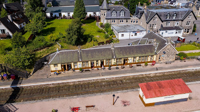
 A blog entry a little off topic tonight. We the Railway were lucky to have “Speyside Drone Services” come in for a session at Boat Of Garten. Hear are some pictures from the day. For any enquires his details are below.
Info@Speysidedroneservices
North signal Box from above. I do need to clean up a bit!

Boat Of Garten looking South.

Boat Of Garten looking North.

Boat Of Garten.

Golf course looking South.

A view from above.

Looking South.
A very clean and tidy station.

Looking South 

The water column. 

I think this photo says it all.
Boat of Garten South Yard.

Boat Station looking North.

A view looking South.

Looking into the North yard at Boat of Garten.

Looking South.

Morley’s shed, with Milton Lockin in the back ground.

Different view looking north.
Looking South.

View of the golf course.


Please any photos that are used please credit them to Ronald Sharp. Of Speyside Drone Services. 
Info@Speysidedroneservices.co.uk
07932522580.

Wednesday 5 August 2020

Signal works, inside and out.

Since the last blog, the time has been spent running string lines and well have a look and a read and you will see.

So this how the box was looking after it’s tidying up session. All the equipment squeezed into the Highland Railway half of the box. Part of the “big” plan for the signal box is to try and return it to how it looked at the end of it’s BR days before the Strathspey Railway took over it.


This is a lovely picture of Boat of Garten North signal box. It is thought to have been taken in 1957. You can see how the block shelf is in two parts. The lower half is over the original Highland Railway half of the signal box before it got extended, with the coming of the GNoS line from Nethy Bridge. 


This second picture, also thought to have been taken in 1957. Shows the writing desk in the GNoS end of the signal box with the rely cabinet below it. You can also see the two phones on the wall. I think there will have been a third phone somewhere in the signal box, but unfortunately you can not see it.


To try and recreate the box close to how it was, in what we think was 1957 the phones have been moved from the south end of the signal box to the north end. The current writing desk has been moved as well but it is intended to find a relay cabinet and for the writing desk to sit on top of it. There is also thoughts of putting in a key token machine. At this time purely for achieving the look of the old box. Although in the future when we do get to Grantown on Spey. There will be a need for a key token machine.


Unfortunately not the best of pictures but you can see how the box looks with the telecoms equipment being moved.


Moving outside, more work has been done on the wire runs for the signals. String lines have been run out, stakes put in the ground and pulleys attached. From the signal box to the bridge and over the other side.

Number 4, the shunt signal for going into the sidings has been mounted, pedestal wheel screwed down and chain put on. Number 16 signal, the section starter has now got its wire crank mounted.


This is the flat wheel in the down cess, with it’s wire rope in place waiting for the wire to be connected. You can see the string line that has been used to get the wheel in the correct position.


This is a nice view of the detector of the “B” end of the points with the flat wheel screwed down and string line attached 


This picture shows you, all the work that has gone in at the “B” end. Giving you a clear view of all that has been done.


This is a look at the wire run north of the bridge. Still some work to do but it’s all a work in progress and not the finished job.