Monday, 17 August 2020

Drone photo shoot

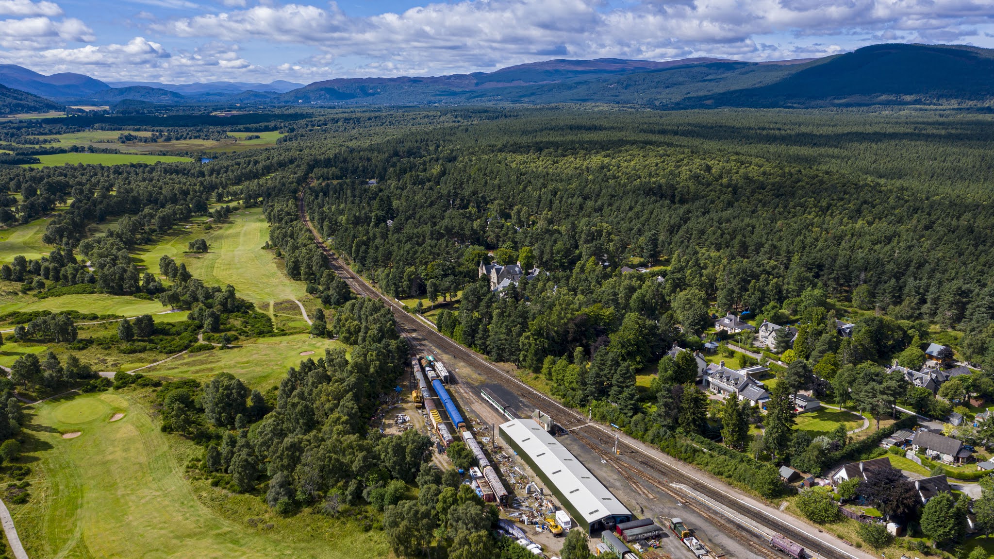
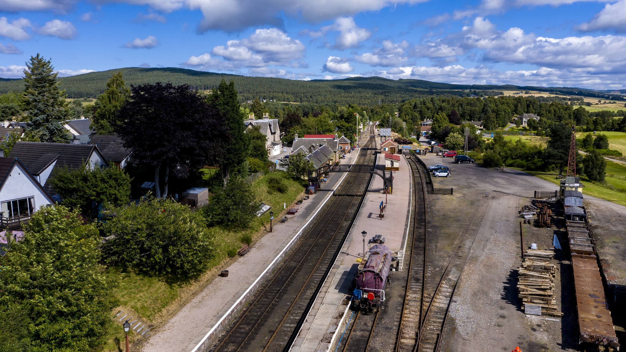
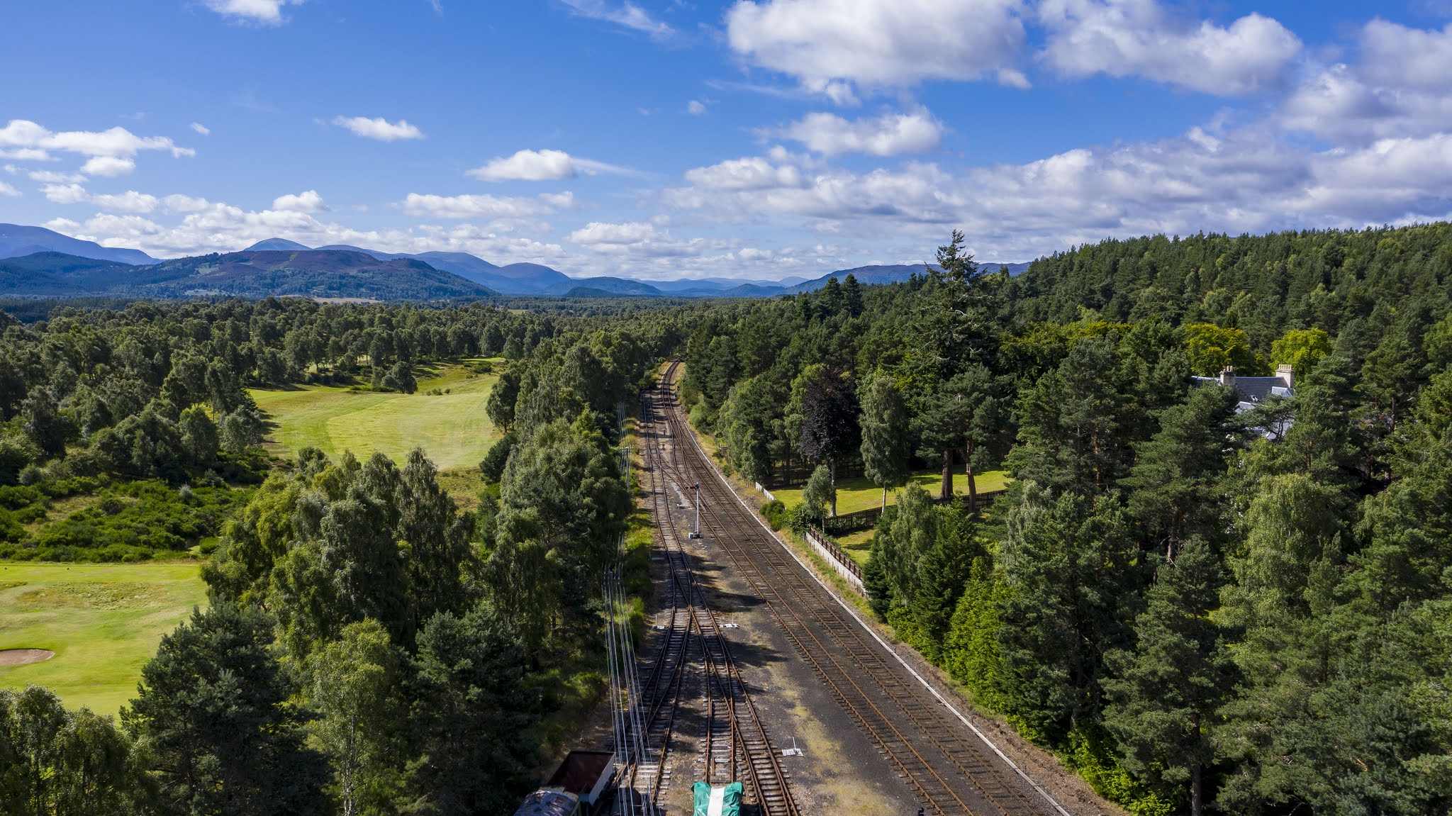
 A blog entry a little off topic tonight. We the Railway were lucky to have “Speyside Drone Services” come in for a session at Boat Of Garten. Hear are some pictures from the day. For any enquires his details are below.
Info@Speysidedroneservices
North signal Box from above. I do need to clean up a bit!

Boat Of Garten looking South.

Boat Of Garten looking North.

Boat Of Garten.

Golf course looking South.

A view from above.

Looking South.
A very clean and tidy station.

Looking South 

The water column. 

I think this photo says it all.
Boat of Garten South Yard.

Boat Station looking North.

A view looking South.

Looking into the North yard at Boat of Garten.

Looking South.

Morley’s shed, with Milton Lockin in the back ground.

Different view looking north.
Looking South.

View of the golf course.


Please any photos that are used please credit them to Ronald Sharp. Of Speyside Drone Services. 
Info@Speysidedroneservices.co.uk
07932522580.

Wednesday, 5 August 2020

Signal works, inside and out.

Since the last blog, the time has been spent running string lines and well have a look and a read and you will see.

So this how the box was looking after it’s tidying up session. All the equipment squeezed into the Highland Railway half of the box. Part of the “big” plan for the signal box is to try and return it to how it looked at the end of it’s BR days before the Strathspey Railway took over it.


This is a lovely picture of Boat of Garten North signal box. It is thought to have been taken in 1957. You can see how the block shelf is in two parts. The lower half is over the original Highland Railway half of the signal box before it got extended, with the coming of the GNoS line from Nethy Bridge. 


This second picture, also thought to have been taken in 1957. Shows the writing desk in the GNoS end of the signal box with the rely cabinet below it. You can also see the two phones on the wall. I think there will have been a third phone somewhere in the signal box, but unfortunately you can not see it.


To try and recreate the box close to how it was, in what we think was 1957 the phones have been moved from the south end of the signal box to the north end. The current writing desk has been moved as well but it is intended to find a relay cabinet and for the writing desk to sit on top of it. There is also thoughts of putting in a key token machine. At this time purely for achieving the look of the old box. Although in the future when we do get to Grantown on Spey. There will be a need for a key token machine.


Unfortunately not the best of pictures but you can see how the box looks with the telecoms equipment being moved.


Moving outside, more work has been done on the wire runs for the signals. String lines have been run out, stakes put in the ground and pulleys attached. From the signal box to the bridge and over the other side.

Number 4, the shunt signal for going into the sidings has been mounted, pedestal wheel screwed down and chain put on. Number 16 signal, the section starter has now got its wire crank mounted.


This is the flat wheel in the down cess, with it’s wire rope in place waiting for the wire to be connected. You can see the string line that has been used to get the wheel in the correct position.


This is a nice view of the detector of the “B” end of the points with the flat wheel screwed down and string line attached 


This picture shows you, all the work that has gone in at the “B” end. Giving you a clear view of all that has been done.


This is a look at the wire run north of the bridge. Still some work to do but it’s all a work in progress and not the finished job.

Saturday, 25 July 2020

Boat of Garten, North Box, Signal Work

Signal works for Morley’s!

The work done at present is a bit like a wind up clock , each part needs to be working in unison to create functionality and so little tedious jobs that are time consuming have as much benefit to the project albeit unseen.


The first of the unseen Jobs was to get the pedestal wheels in under the box. Not the simplest of jobs to do! With the aid of string lines, rulers and power tools. Each wheel has been placed into it’s correct position, for receiving the wire from the lever tail and passing it out to the flat wheel outside. Which then sends the wire on it’s way to the signal. If anyone of these parts is out of alinement, then the harder the pull on the lever will be. As well as more likely to have faults in the future. Within this picture you can see that all the pedestal wheels have been placed and screwed down.

The way that the existing signals have been attached to the lever tail is with chain and S clips. To maintain the look and to keep everything uniformed. The same Practice has been applied with the new signals that we are putting in. This is a picture of the first trial fitting. It took lots of attempts to get the correct length of chain for each lever but with a bit of perseverance it all came right.


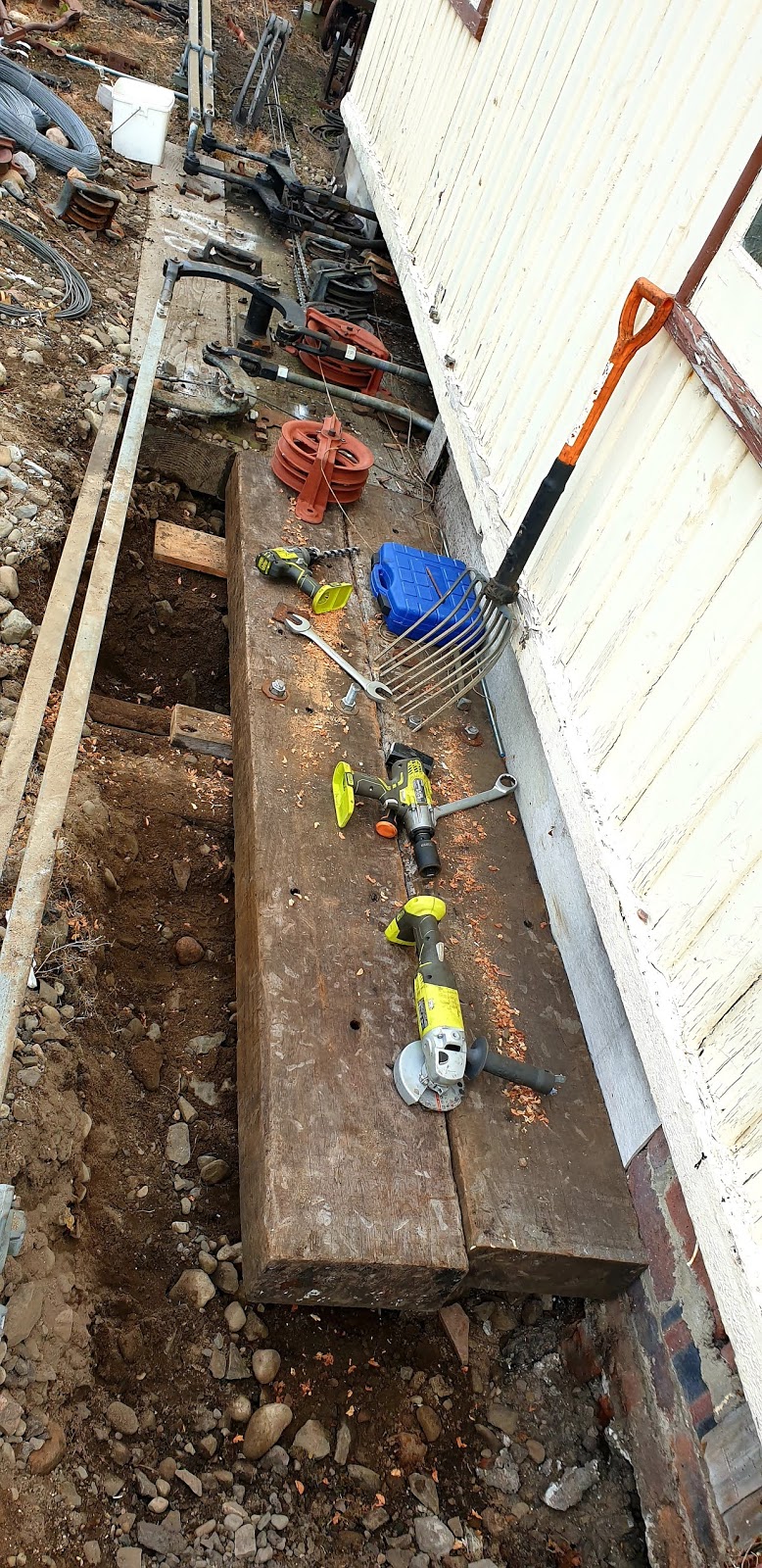
On the outside of the box it was found that the front table needed to be extended to get the flat wheel on for number one signal. So more digging, drilling and power tools. Two new timbers Where added, all just for one wheel. Although now looking at it. It dose tidy up the front of the box and makes it look like it has a much bigger frame within the signal box. As it did back in the day. Also in this picture you can see how the flat wheels have all been placed out first, with the aid of string lines to get the correct position. The other problem that complicates things is the need to get the wires in the correct order. Signal number 16 needs to be the wire nearest the signal box as it is the signal closest. As well as the signal being on the left hand side of the wire run. Then signal number 4’s wire needs to be the second wire from the signal box side. It is the second closest signal and is on the left hand side of the wire run. Both signal wires for 1 and 7 signals both go over the bridge. 1 drops away with a flatwheel on its left to go under the track to the signal. This is the third wire from the signal box side. While 7, the closest to the track, runs on it’s own all the way to the outer home. It’s been a lot of tea drinking and drawing sketches on the back of envelopes but I hope it all works out well.


Hear you can see the completed job from the outside. All the flat wheels are screwed down, chains or wire ropes coming out from the lever tails. For 17 all that is needing to be done is to run the wire run. Everything is now in place. All other pedestal wheels, flat wheels and wire pulleys are all in place. 16,7,4 and 1, there is still some work to do. The stakes need to be put in the ground every 9yrd to hold the wires( about 50 to put in). The wire pulleys to be fitted to the stakes, Two flat wheels to be positioned And screwed down, for number one signal. Plus a some other jobs! The list is getting smaller!

Davie Dow has helped out with creating and mounting of the pulley in the middle of the bridge to take the signal wires. For this I am most grateful.


 A little bit more work has been done on the outer home. With the ladder now up, and signal arm put on. This in it’s self was no easy task as the signal is 28ft tall with a ladder of 29ft ish, at an incline of  1 in 12. This is the standard for this type of LMS post. The arm will be bagged up before any trains are running and will only be de-baged when coming into use. Once the project is completed. This is  hopefully at the start of next season.

Sunday, 12 July 2020

Morley’s sidings

Morley’s sidings. 12/07/2020

Time for another update on how work is progressing on the Morley’s sidings project. As you will see in the pictures below things have been progressing well. It’s like a mercano set! Everything fits together but you just need to find the correct parts. There has been a lot of time spent going around the railway looking for the correct parts but the end result for this has been Very good.

So the first of the jobs was to get the drop lugs on the points ends facing the correct way and to get the alinements correct between the points to the detector. As well as the alinement of the wire run from the detector to the base of the signal.


 This is the first attempt at getting the alinements correct, unfortunately this did not work out. The connection rods and swords just did not fit well for the job. So it was time to look for better parts on the railway.


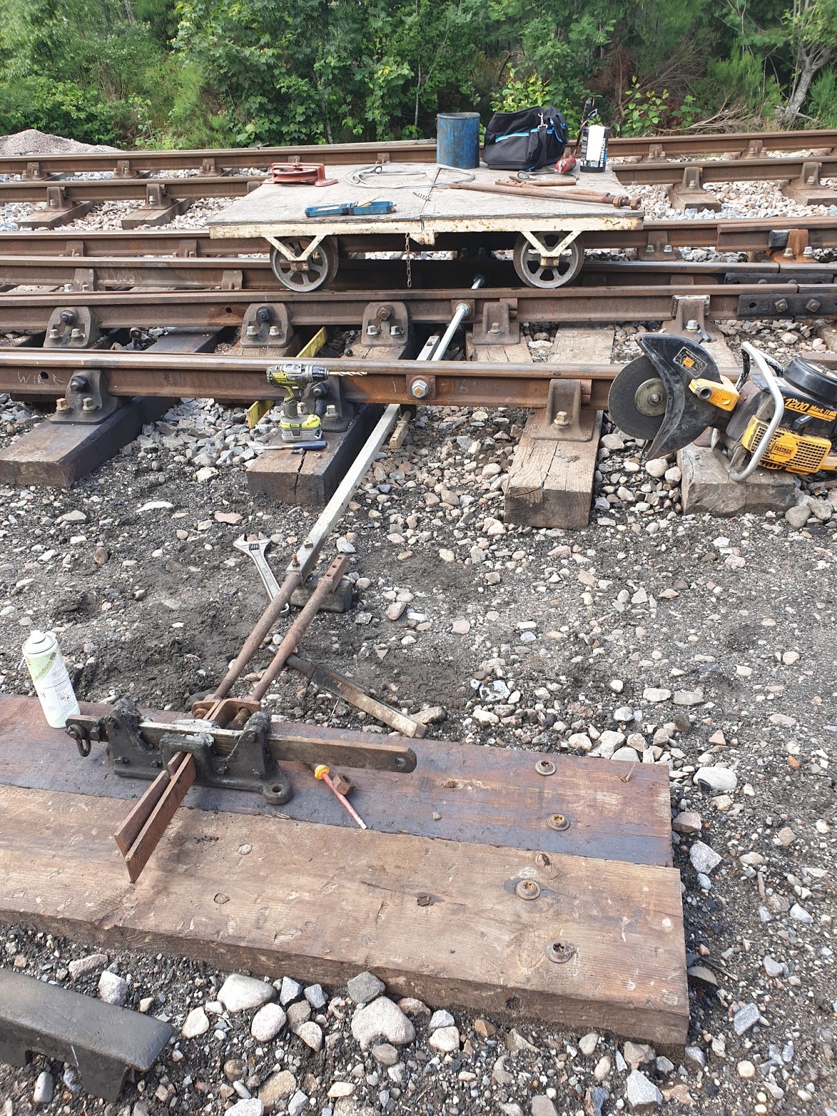
This is the finished job! Detector is fitted, better swords and connectors Rods was found and replaced. Points were tested and correct. Very happy with the outcome. Just to remind you all. The threaded bar at the front of the points is acting as the sole plate to ensure that nothing can move.


 Now this is a hard one to explain, at this point some time was been spent sorting out cables for between the signal box and the two location cases that have been installed at the new outer home. 400 yards of 19core and 400yards of 2 core cable have been prepared which the P-way were ask to  help pull out.
 The hope was to get a bit more done on the outer home but unfortunately it was not to be. The ladder that had been selected for it turned out to be to badly damaged. Another needs to be found. With it been on the roadside for all to see, would prefer it to be as perfect as possible.
Still managed to get the balance weight up and mounted. It’s not much but it’s a step in the right direction.


 This is the new section starter now with it’s ladder fitted. The hoop at the top is damaged and needs replaced, which I anticipate to have done on my next visit and weather permitting a coat of paint.
This signal I am really getting quite fond of. Now fitted with it’s ladder, balance weight leaver and crank fitted at the bottom. All that it left to do with this signal is the wire run and the signal lightning circuit.


A little bit more  has been done on the “A” end of the points , I’m really pleased to how this has turned out. On the left hand side of the picture you can see the newly pulled out cables running from the signal box to the outer home. The cables still require to be jointed.

 This photo was supplied curtesy of Graham Maxton . He has challenged us to recreate this picture. Would it be easier to create  it from the signal box or from up one of the signals?
 This picture is from the new section starter, I believe that the  previous or original Starter signal was on the north of the old bridge. The new shed sits on top on the old sheds foundations.
 This is the view from the North signal box so I don’t think the original picture could have been taken from hear.
 Again this is taken from up the top of the new section starter but this time looking south towards the station. Been qualified and permitted to build and climb these structures is definitely a perk of the job. You can appreciate what the railway has and what “Team Strathspey” has created.
 A bit of time has been spent cleaning out the North signal box. Getting all the equipment that should not be on the operating floor out. If anyone is willing to help and enjoys painting then hear is a nice little job for you. Please let me know if willing to help.
 Looking from the opposite end much better but still some work to be done.
The S&T vans on the way back to the sidings at the south end of the station after collecting all the materials out of the North signal box.